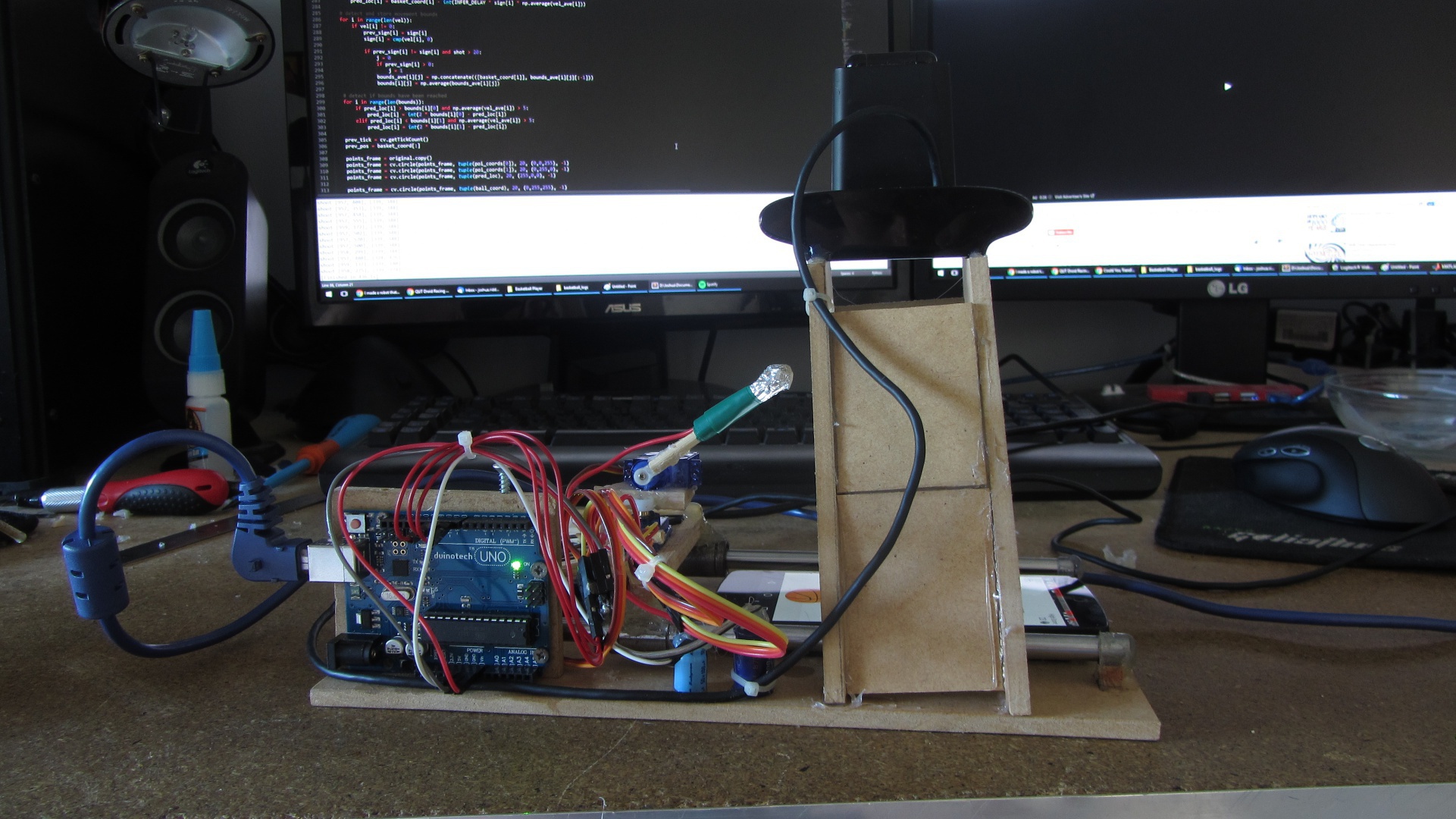
Messenger Basketball Playing Robot
Quick Links
Internal
External
Overview
Facebook Messenger recently released a minigame in which players try to take shots at a basketball hoop. The hoop is originally still but begins to move as your points increase. The aim of the game is to beat your friends in Facebook group chats. I don’t have the patience for tedious games such as this, so I made a robot which plays it for me.
The high score of the robot is 157 so far, the highest human score I have heard of from my friends is 45.
(Note the wire plugged into the phone is just for charging purposes)

The robot uses a webcam to track the basket and ball on the phone screen. It uses a simple 3 degree-of-freedom arm for interaction with the screen. My aim for this short (2-3 day) project was to have a robot which plays it ‘as a human would’, meaning, there is no software trickery by using tools such as adb.
Computer Vision
I used OpenCV bindings for Python2.7. Python is my strongest language, and handles a lot of the low level memory stuff for me, so it was well suited to this quick prototype.
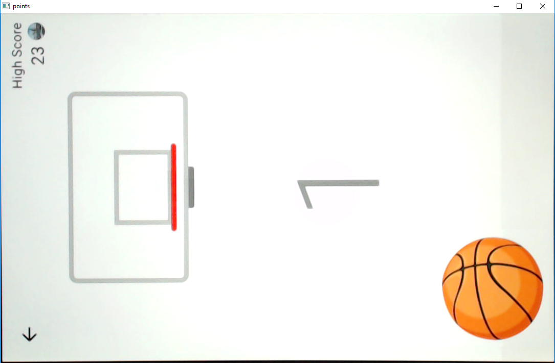
The computer vision side of the robot takes in a raw image, crops it, and applies a colour threshold based on colours defined by me. Shown below is the image just for the basket, the ball is visible because they are a ‘similar’ colour. This ‘error’ makes little difference as I apply an area filter later on to choose between the two objects.
Left is the original cropped image, right is the filtered binary image after noise filtering.
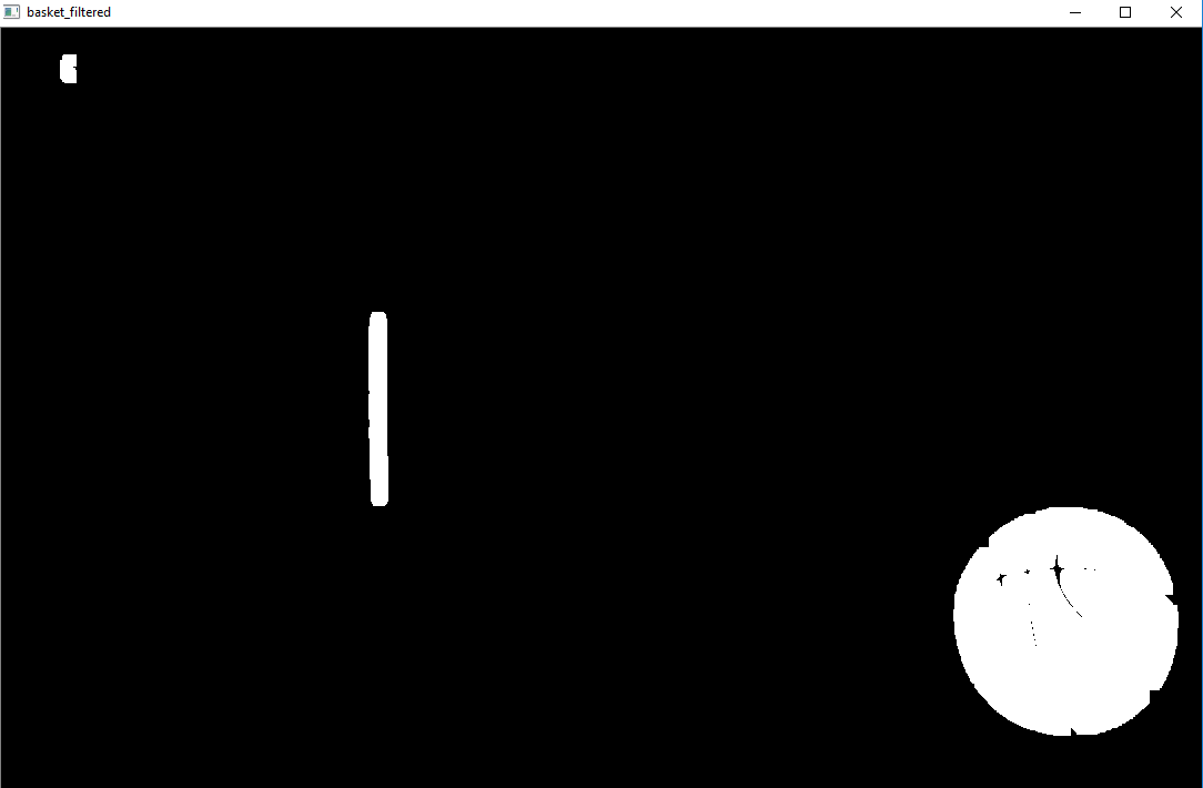
Contour finding operations are then performed on the above binary image. Contours are filtered by area and position (e.g., the ball will never be on the left side of the screen) to identify the ball and hoop. The centroid of these contours is then taken in order to acquire an (x,y) coordinate of the two points of interest.
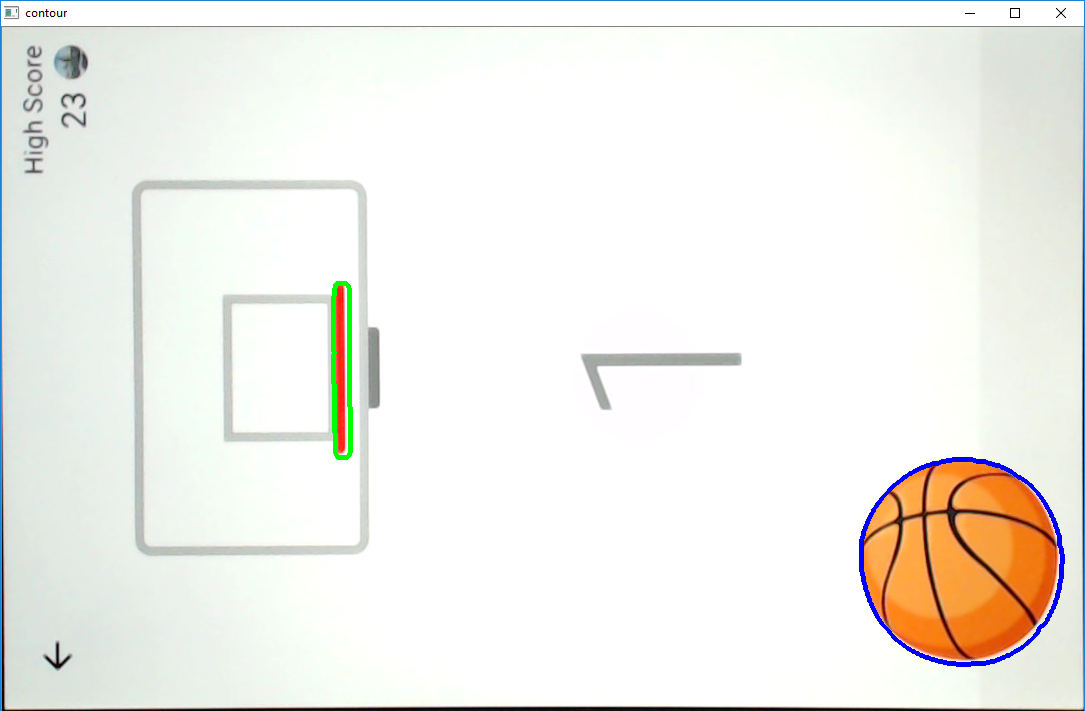
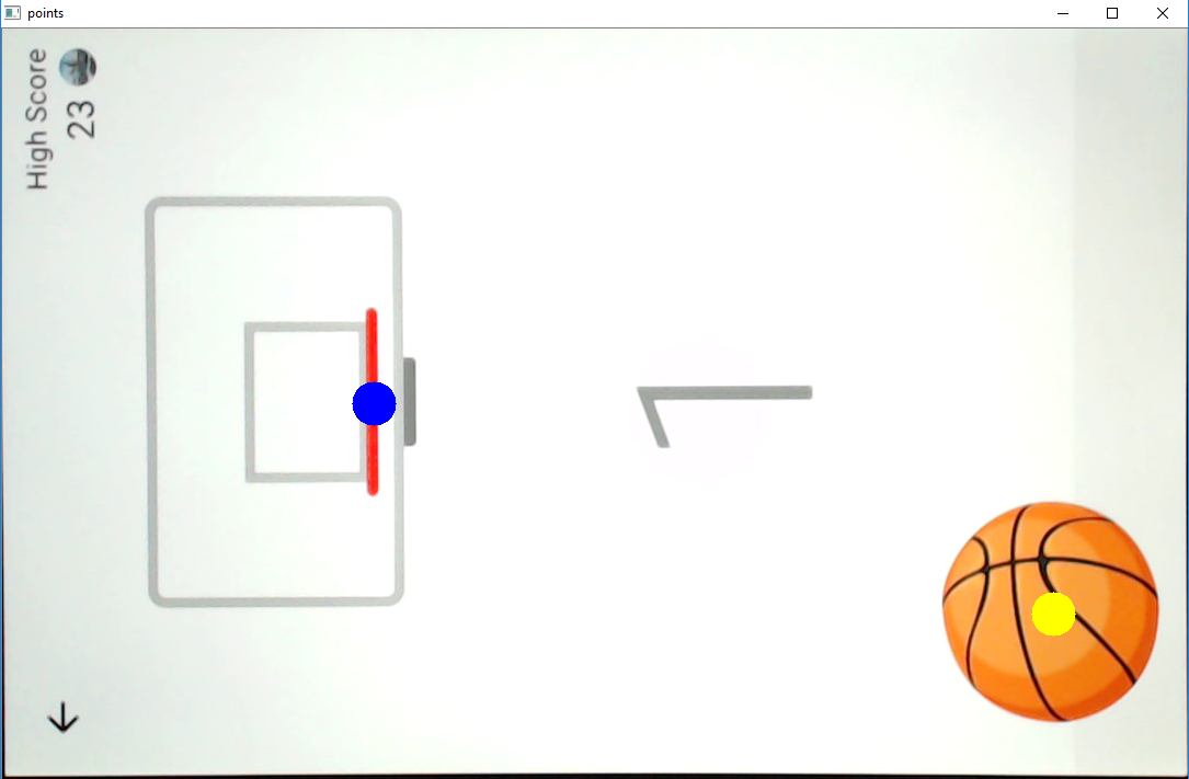
The green dot shows the current position of the hoop and the blue dot is the predicted position. I specify the prediction time, and this is tuned to suit the speed of the robotic hardware. I have found that using a constant value works very well.
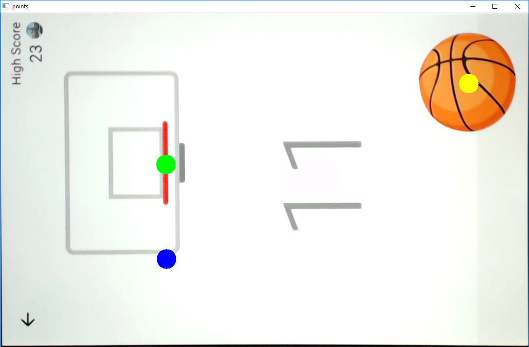
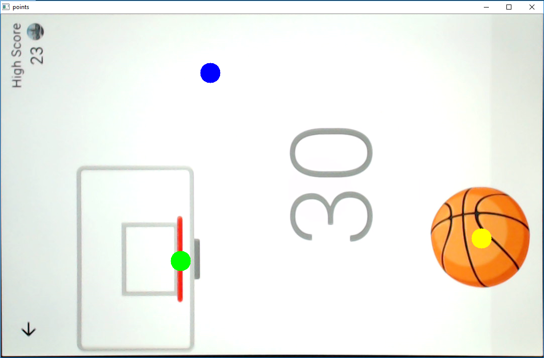
When the hoop is stationary the hardware is sent commands such that it will flick from the ball directly to the hoop. When the hoop is moving the program will wait until the hoop is directly above the ball. This exploits the fact that the robot has a linear slider which runs vertically and allows the throw to be extremely precise. In fact, generally speaking the robot makes more errors in the 0-10 points range (when the hoop is still), than it does from say 10-100.
To send to the robotic hardware, the (x,y) coordinates of the screen pixels are firstly converted to the (x,y) coordinates of the robot using a linear transformation. The robot (x,y) coordinates are then translated into motor degrees using an inverse kinematics model I modelled based on simple trigonometric functions.
Robotic Hardware
The robot consists of 3 ultra cheap ($USD3-4) servos for actuation and an arduino to convert the serial input from the computer vision program, into a low level signal for the servos. The Arduino acts only as a converter and does not perform any logical operations. This was done only because uploading to the arduino is a slow and tedious process when repeatedly testing code.
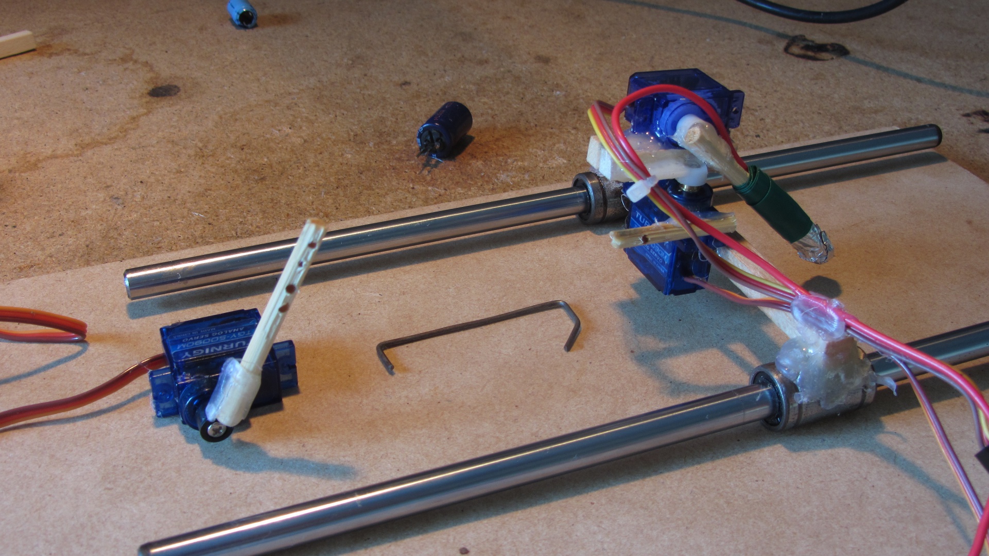
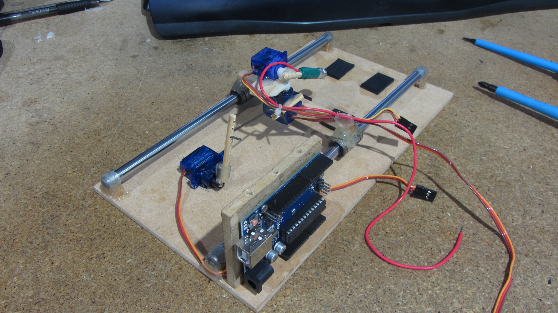
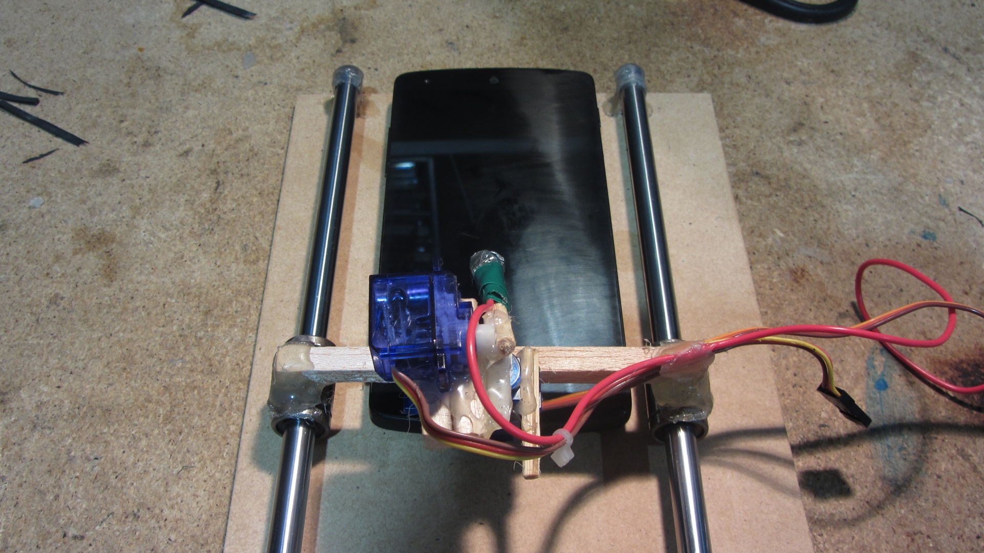
Below are some images showing the build process.
All parts

X-carriage parts and then assembled
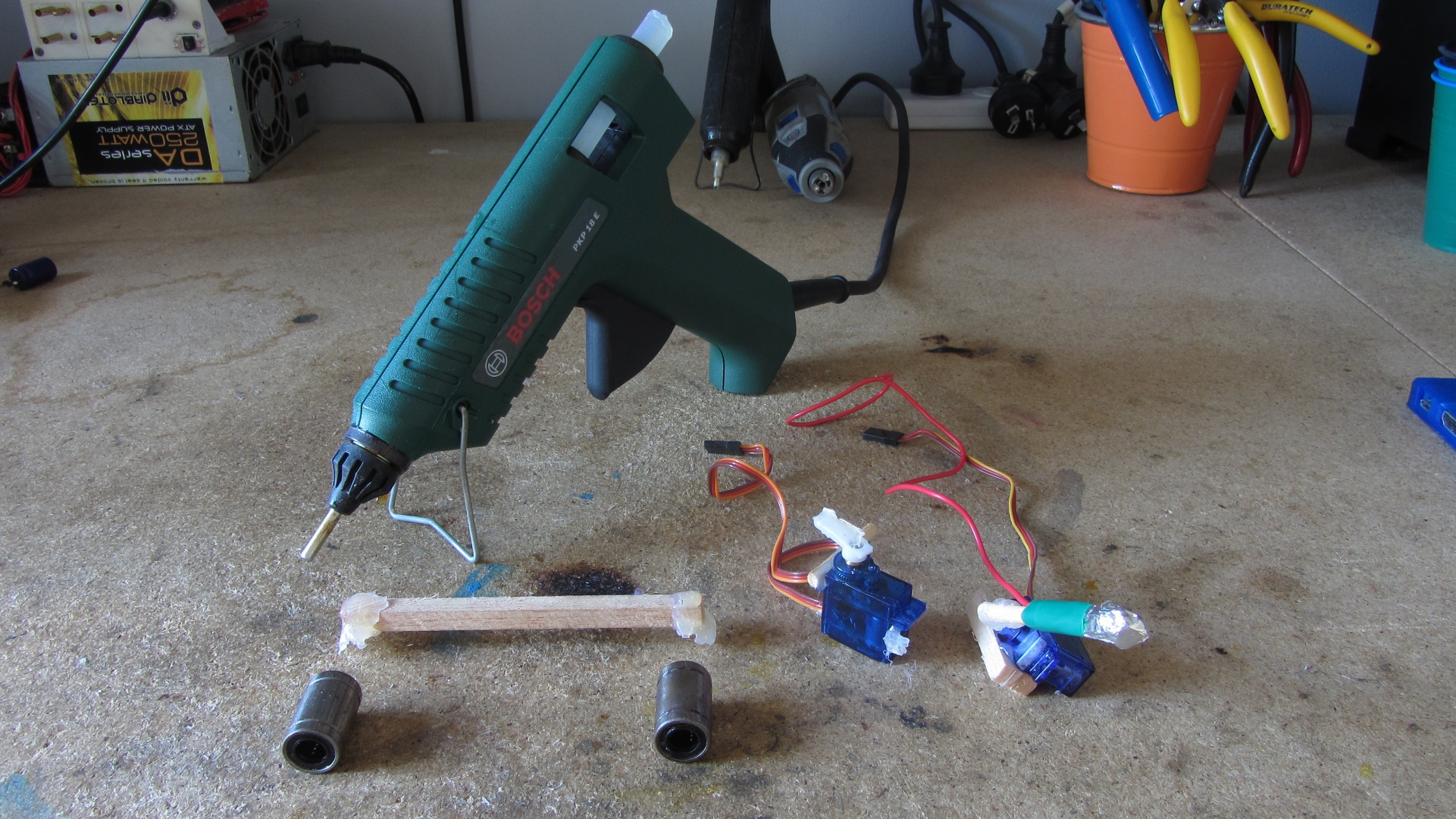
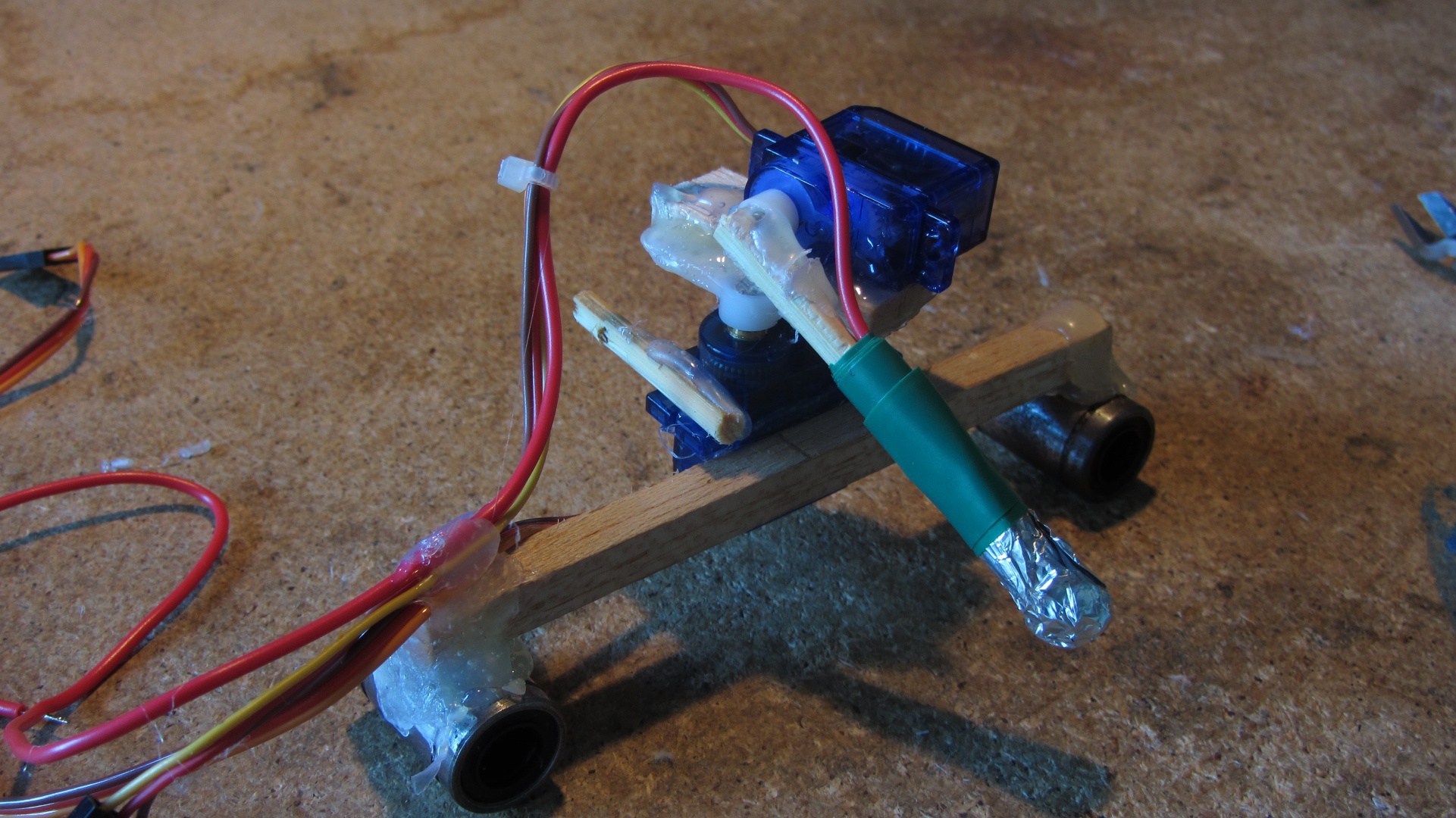
Y-carriage parts and then assembled (with arduino)
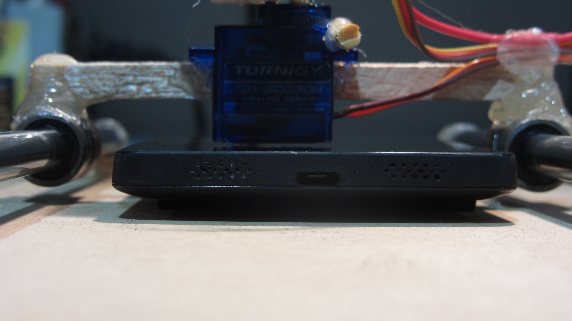
Phone test fit
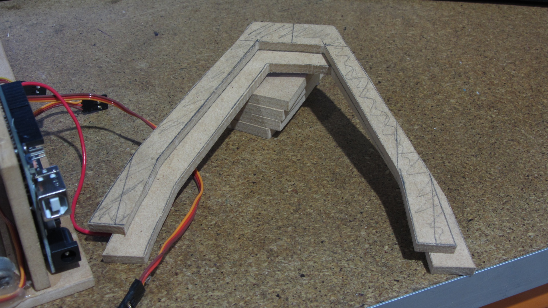
Camera frame parts and then assembled
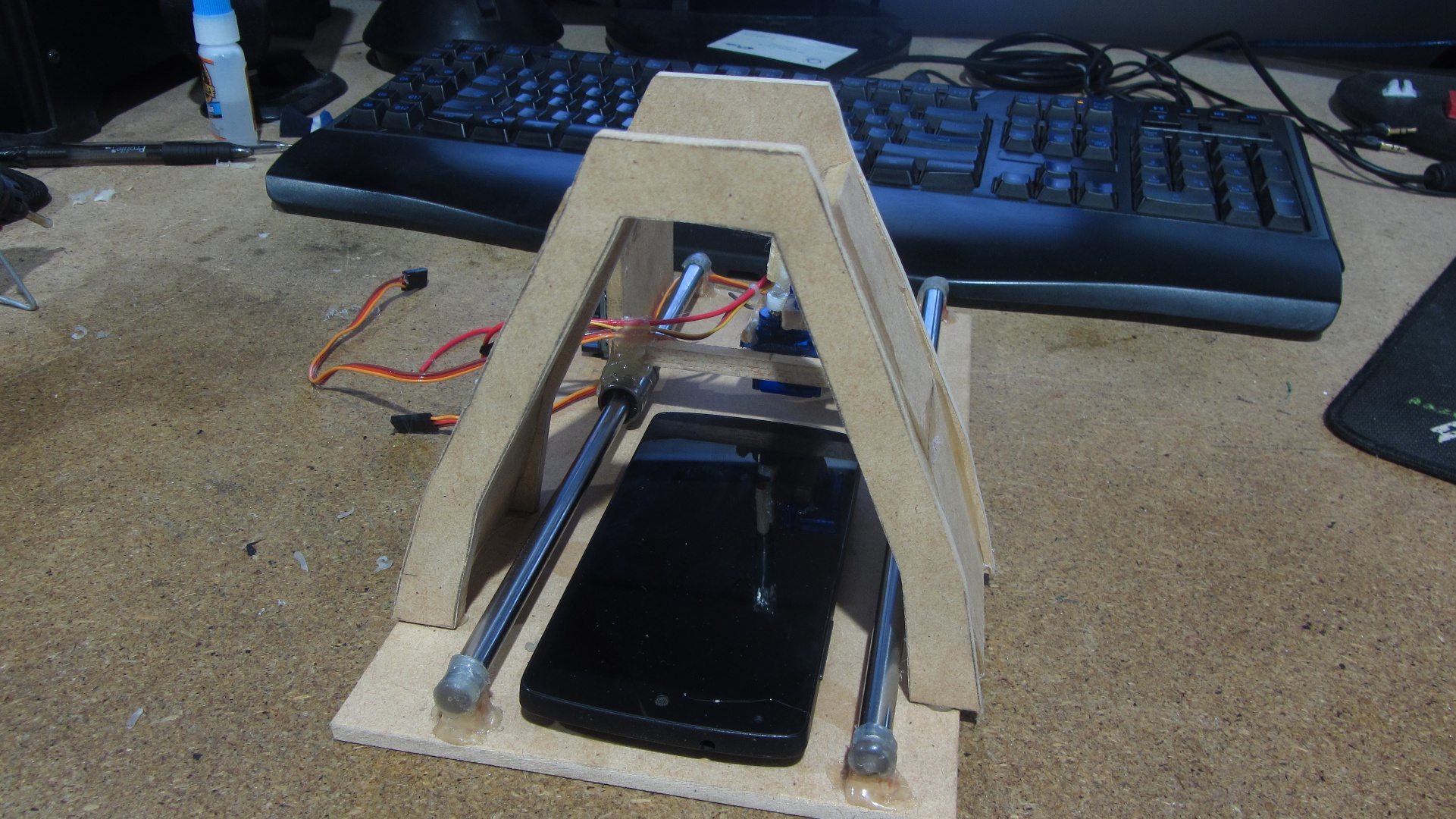
Finished wiring (the angle of the camera mount is intentional to give more space for electronics)
