Low Cost Distance Scanner
Quick Links
Overview
The distance scanner is two SHARP IR Distance sensors mounted onto a 360 degree rotating spindle. This sensor is intended for use on low cost effective Arduino robots, where a laser scanner is out of scope both in terms of processing power and monetary cost.
Aim
The aim of this project was to:
- refine my mechanical design and manufacturing skills;
- gain experience in creating electrical connections over moving parts;
- create a basic distance scanning sensor at a low cost;
- design basic SLAM algorithms.
Hardware
Worm Gear-set
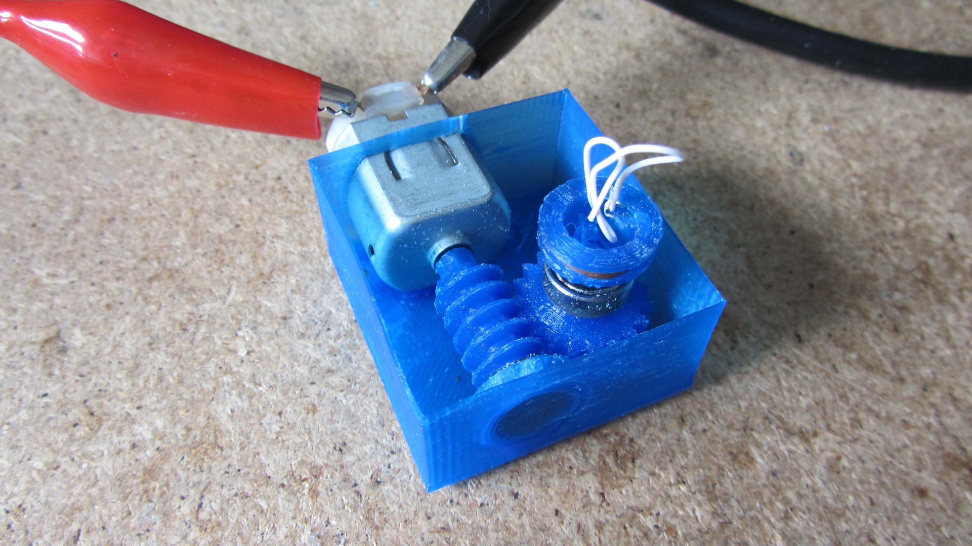
The motor used runs at ~11,000RPM@5V (no load). The maximum gear ratio which could be fitted into the case was 1:19. This was limited by the print resolution.
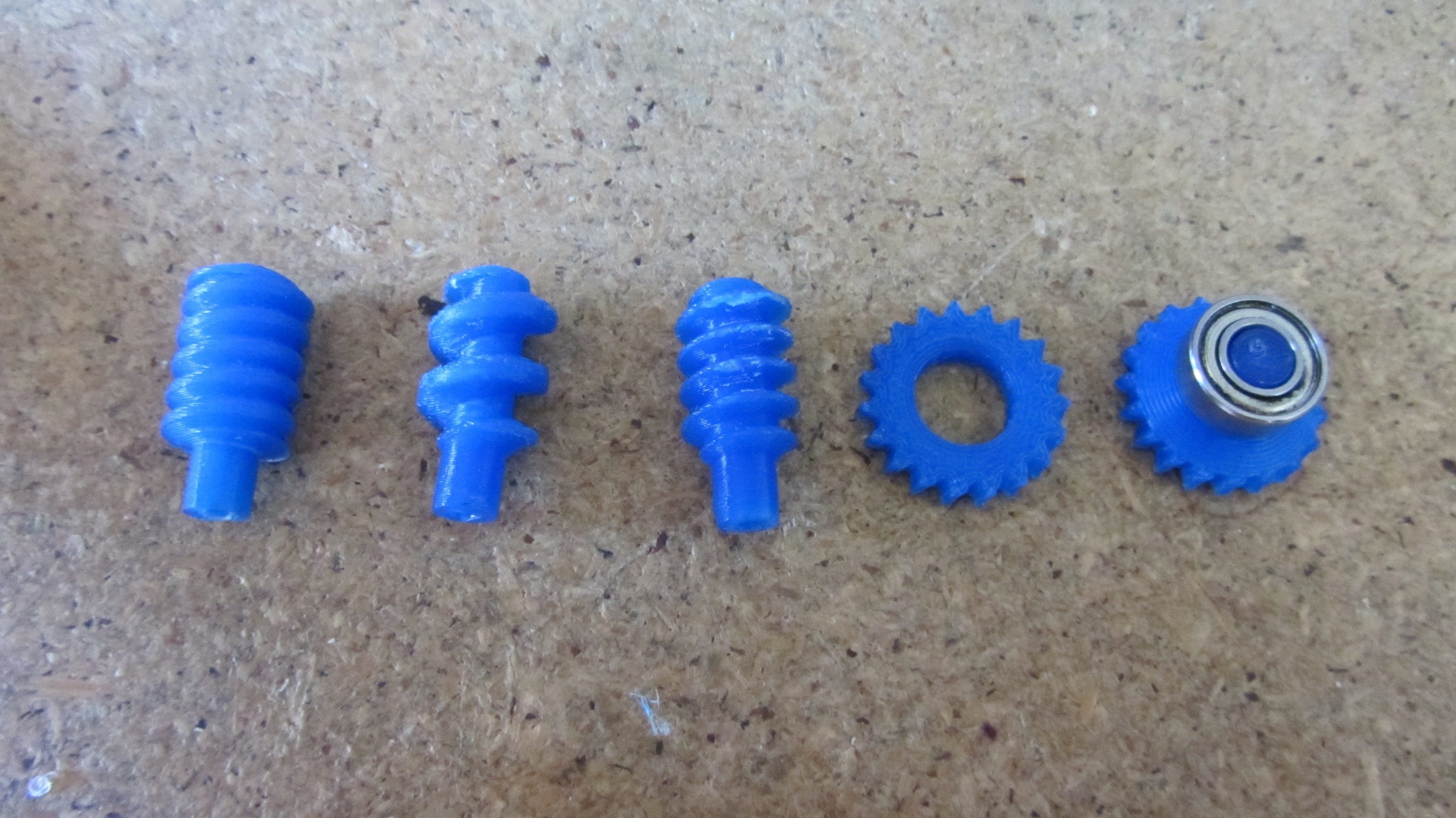
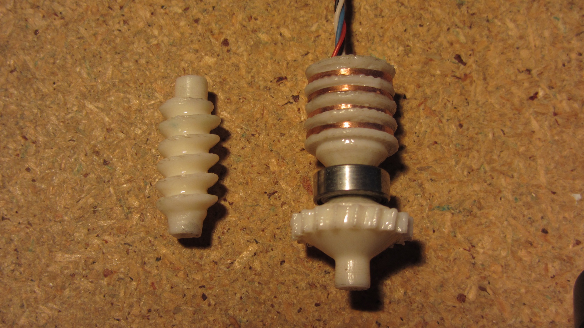
Below are some iterations of the worm gears.
The tested rotor speed was 320RPM@3.3V which although much lower than the original, is still too fast for the sensor. As shown in the data collection.
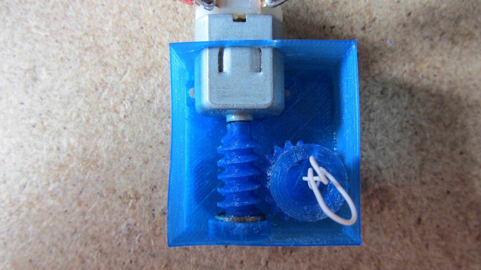
The main issue found during testing was that the gearbox was very loud. This was rectified by changing from PLA to ABS plastic, which can be smoothed using acetone vapour treating, and using thicker walls to prevent vibrations.
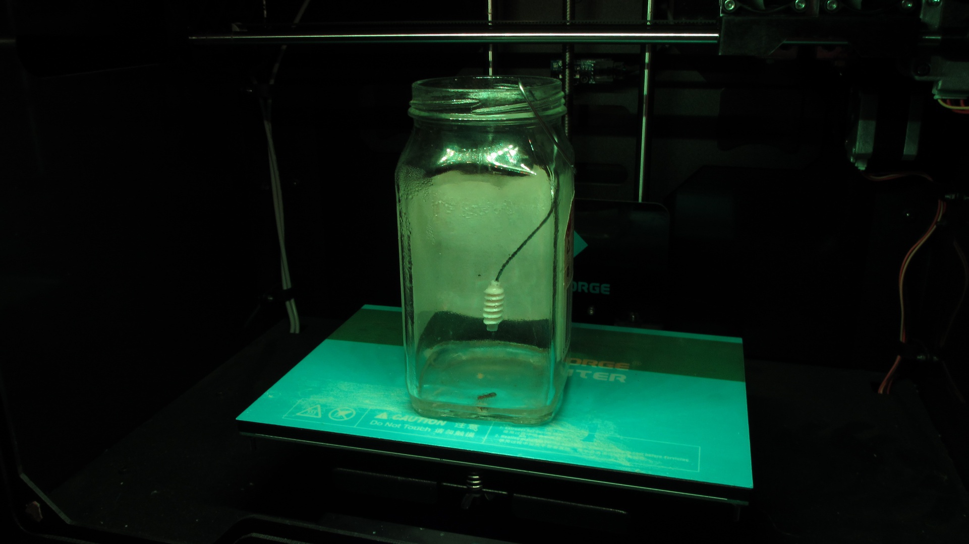
The treated product is shown below.
Rotor
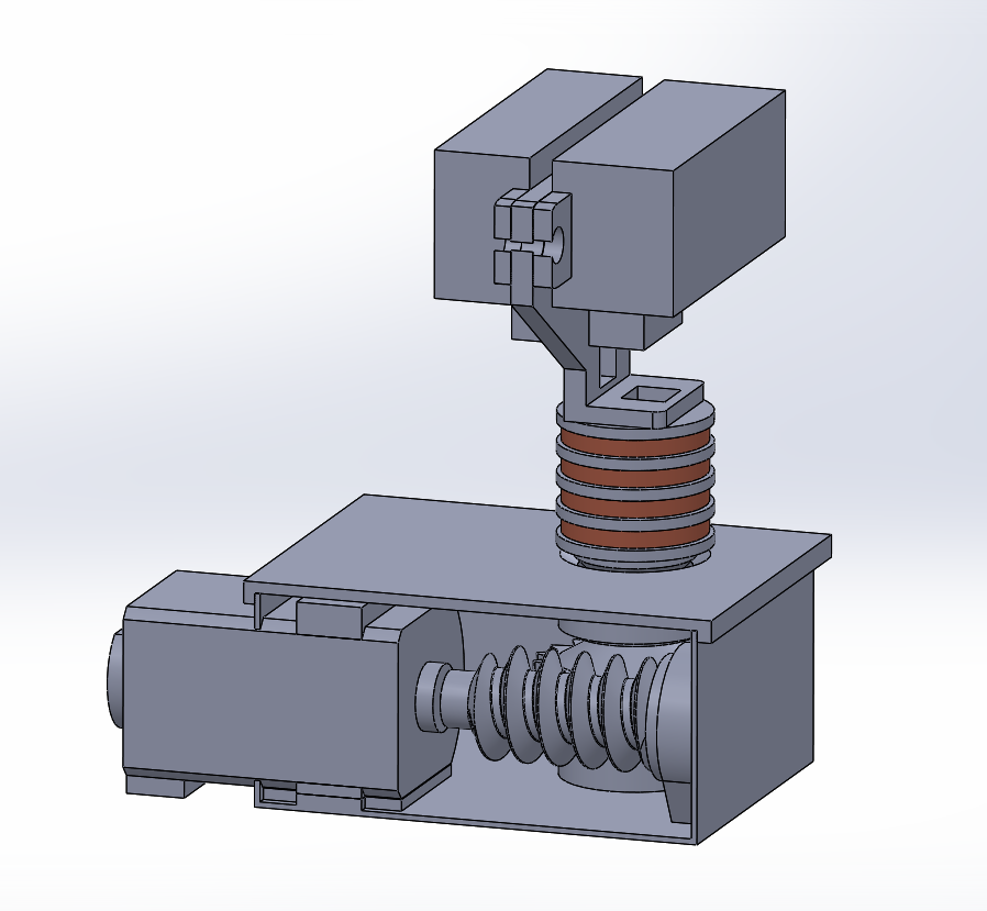
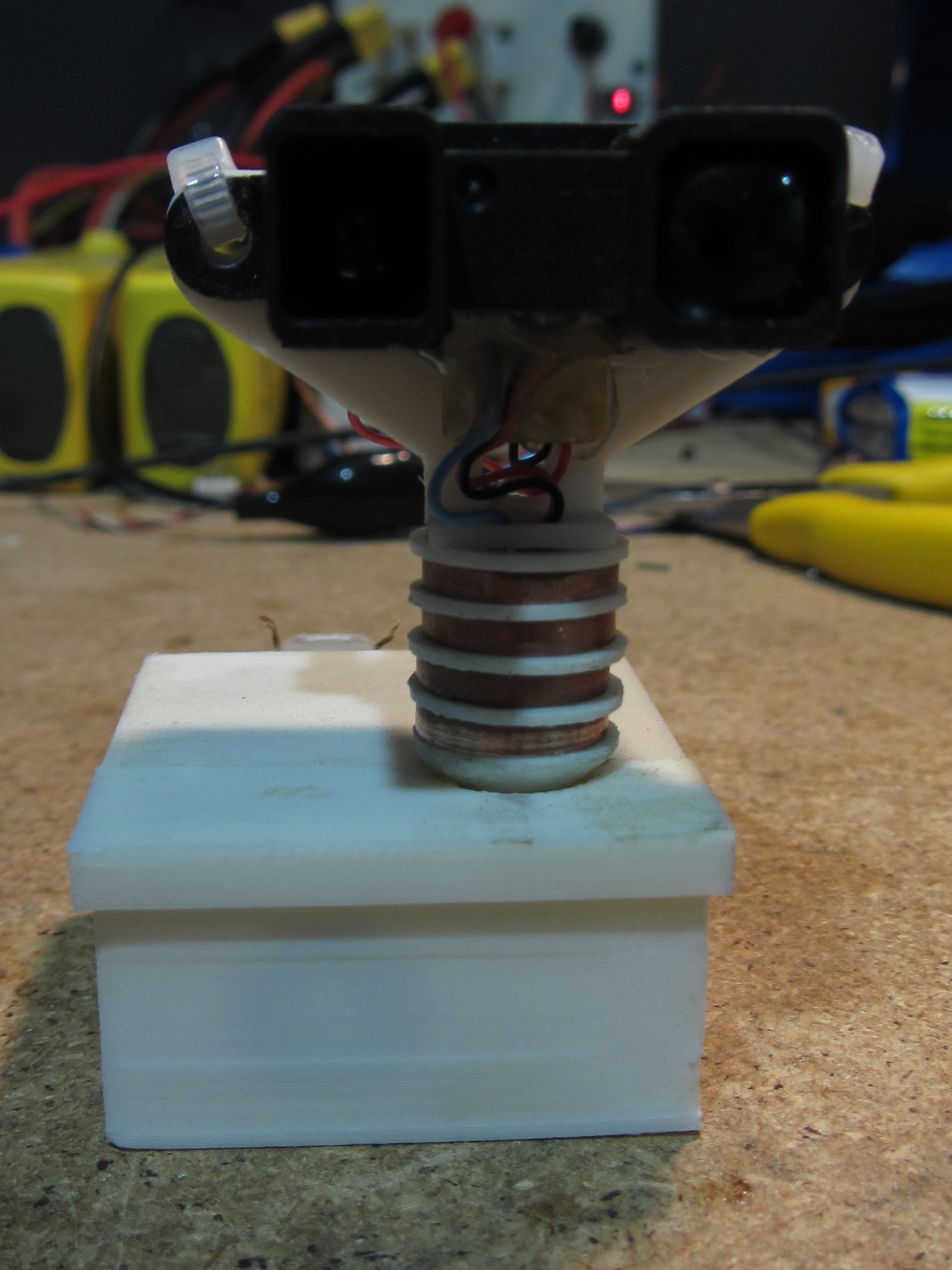
The rotor consists of 4 slip rings (+5V, GND, SIG1, SIG2) constructed using ~1.5mm thick copper piping slices. These were inexpensive to produce and provided a good surface for electrical connection. The CAD model for the rotor is shown below.
The rotor is printed in parts as shown below.
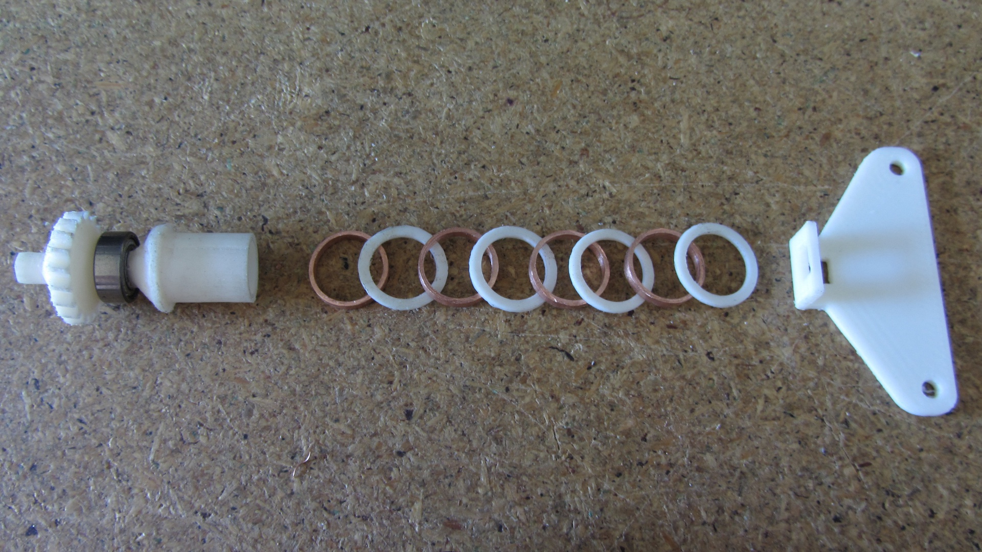
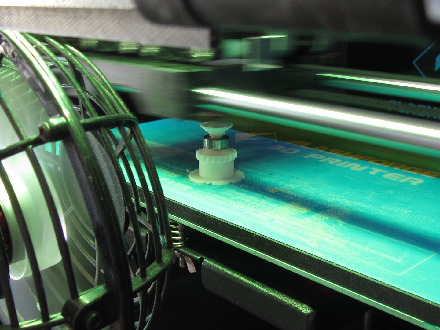
The main shaft part is printed in one piece, with the bearing being inserted during printing (shown left). The copper rings and spacers are placed onto the shaft one by one, with friction holding them in place (shown right).
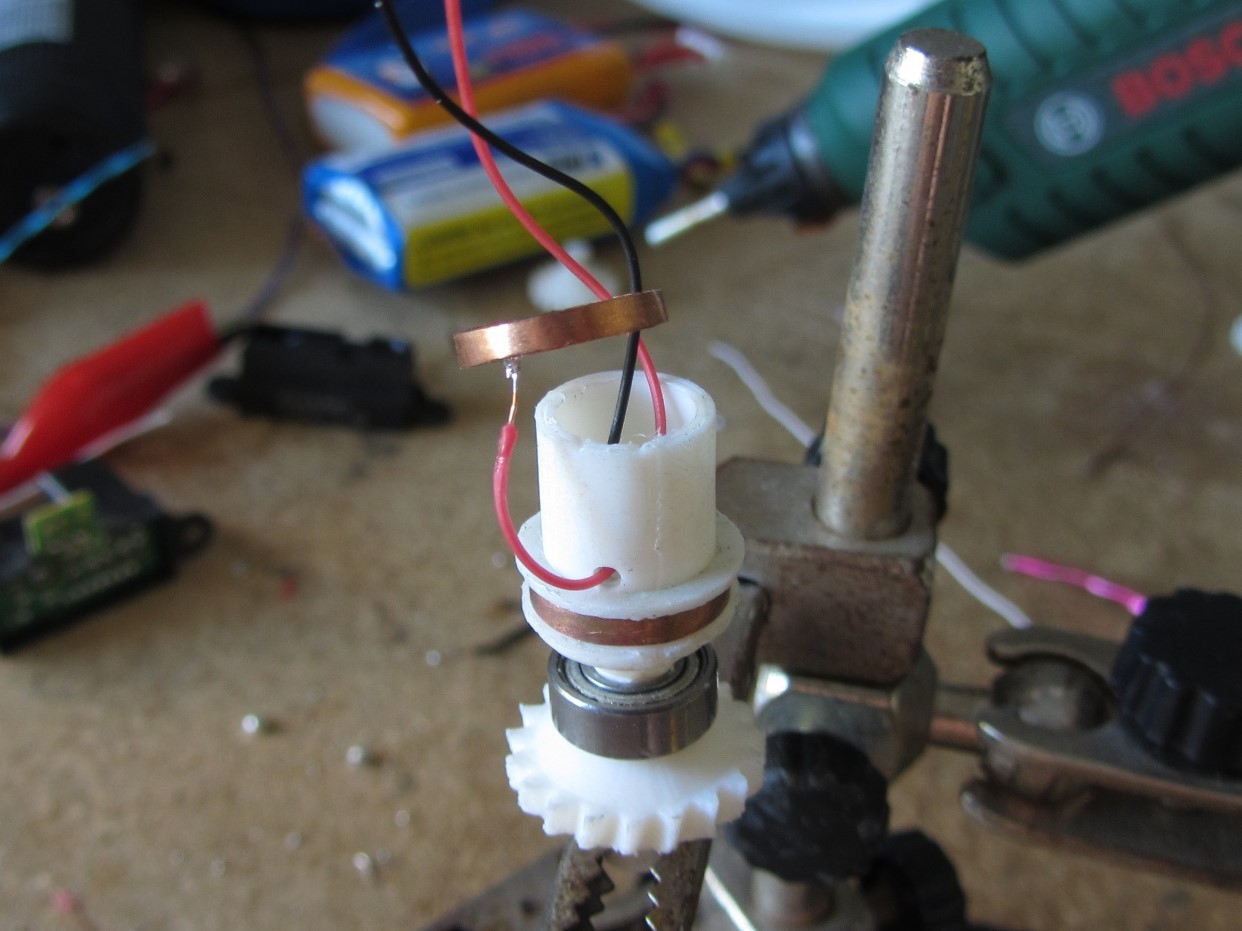
After the rotor is assembled, the top sensor mount is glued on the top, and the wires are soldered directly to the sensor. This makes for a very compact design.
Electrical
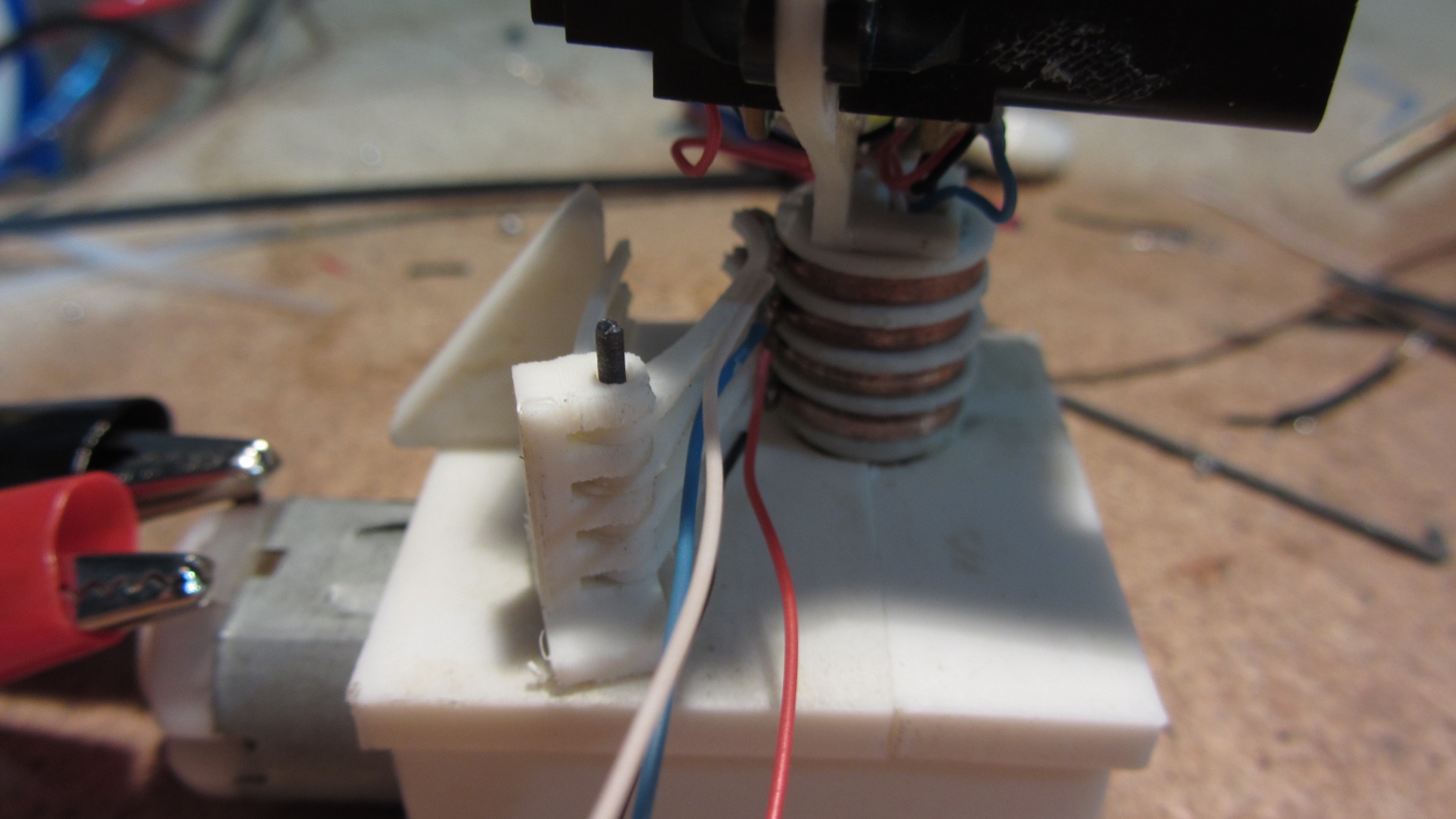
Some simple brushes with plastic springs and copper contacts maintain electrical contact with the rings. Conductive lubricant was also used to combat corrosion and improve connection reliability.
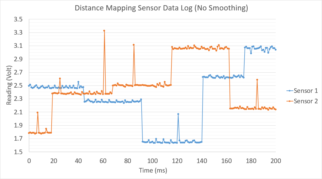
Datalogging was performed to check the integrity of the connection. The data below has no smoothing (either from a capacitor or in software) and shows very little deviation in voltage reading. The almost discretised changes are changing sensor readings (refresh rate of ~40ms).
Demo
Future Plans
At this point, other commitments and interests have taken over from work on this project. I may do a revisit to write some software and get a pointmap out of the raw data from the sensor. Only time will tell.